Aerostream Mk 2 Build Process
Our full build process of how we built Aerostream Mk 2
8/4/20244 min read
Our Build Process:
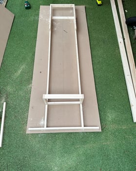
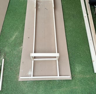
Before diving straight into the deep end and getting a full steel chassis welded, I had to do some designing and prototyping with design ideas. The easiest way to do this is by using strips of pine that are the closest dimensions we could get to the dimension of the steel box section (40mm x 20mm x 2mm). We knew our maximum measurements we could work to due to width and length restrictions. This was 2.5m in length, 82cm in width, and 90cm in height.
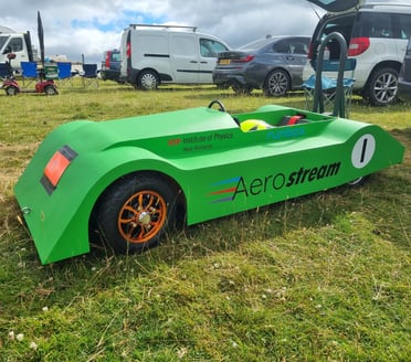
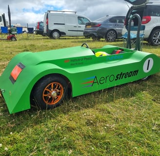
From the picture above, you can see our first prototype. We have made the inside section (where I will be seated) as small as possible. Doing this enables us to use the rest of the width as much as possible with an aerodynamic body giving me the least drag efficient body possible.
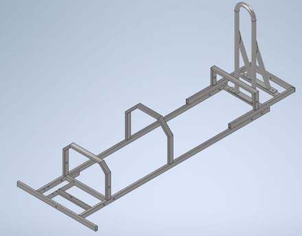
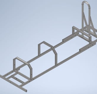
1. We designed our steel chassis in CAD to preview what it would look like. This allowed us to easily modify the design and change dimensions without wasting any material. We were then able to use this CAD design to produce individual and assembly drawings which we were able to provide to the welder in order for him to assemble and weld the chassis as per the drawing.
2. From the picture below, you can see our first prototype. We have made the inside section (where I will be seated) as small as possible. Doing this enables us to use the rest of the width as much as possible with an aerodynamic body giving me the most aerodynamic body possible.
3. We then received our welded steel chassis and checked it all to make sure it was what we expected.
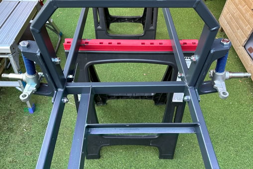
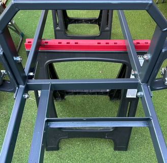
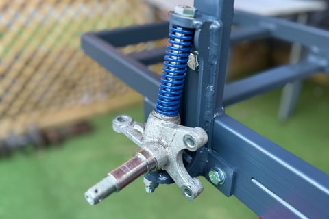
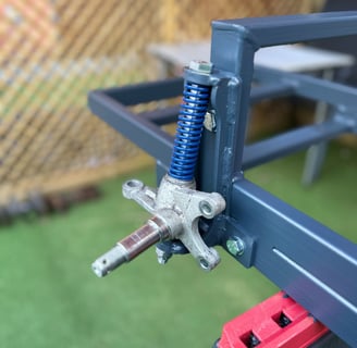
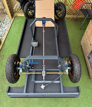
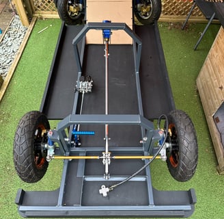
4. Next, we started by assembling the wheel brackets and bolting them onto the chassis along with fitting our suspension springs with the axles.
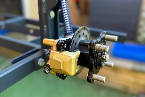
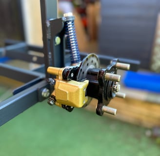
5. After this, the hubs and brake calipers were fitted.
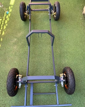
6. The final part of making it a freestanding chassis was to temporarily fit the wheels.
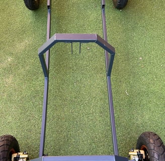
7. In order to make it a full rolling chassis, we fitted the floor and the steering setup (steering column, track rods, steering wheel plate). After this, we added a few other items in order to gauge how much space I would have as well as space available for bodywork. This included: brake master cylinders, brake bias bar, brake pedal and the prototype seat.
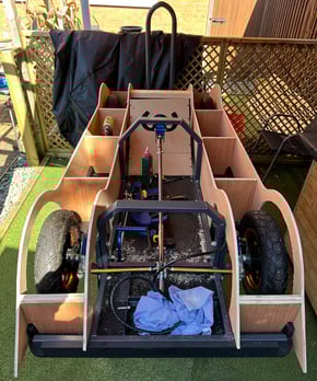
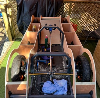
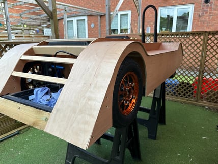
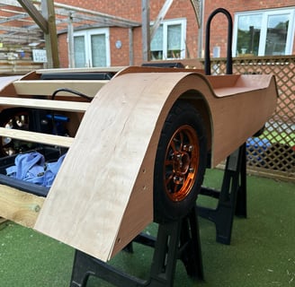
8. To start with the bodywork, we made up some templates from hardboard to ensure the sizing was correct before cutting out 4 x 15mm plywood frames (2 x inside frames and 2 x outside frames). We added uprights between the two frames to give us support. To further add support for the 1.5mm thick Aeroply, we added multiple batons across the wheel arches to give us strength and a gluing point.
9. The Aeroply was then glued in place and nailed temporarily, whilst the glue was setting. We left the glue to dry for 24 hours and pulled all nails out. This was the majority of the bodywork made and our ‘sidepods’ had been formed.
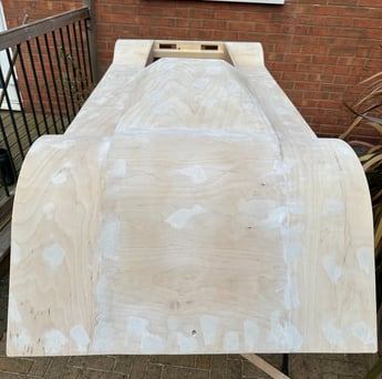
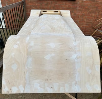
10. Following the same process as the ‘sidepods’, we fixed some batons across the central section and glued and nailed the Aeroply to the centre. We then fixed one flat panel of 9mm ply on the top of the body with two angled pieces to fill in the gap between the ‘sidepods’ and the centre. To finish off making the body we added two internal side pieces to give me some extra protection around my shoulders. Finally, we added another little panel of Aeroply at the back section with a cutout for the rollbar, also we fixed on a rear panel to join it all together.
11. The finishing process of the build was first to fill and sand the body to make it smooth enough for applying paint to it. After this the custom coloured paint was applied as well as the stickers applied across the body.
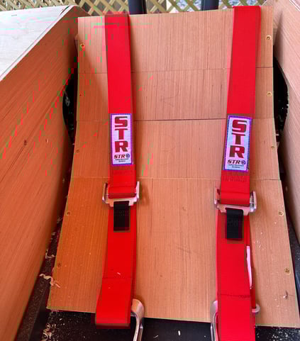
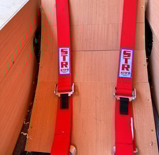
12. Some final jobs we had to do before we were ready to race included: Fitting some foam onto the seat for comfort, a front and rear towing eye for getting towed back up, seat harnesses fixed in place, wheel alignment, print and fit 3D printed steering wheel grips and a general check over on all bolts to ensure no bolts shake themselves loose.